Kyptec Automation® Strengthens Camera Link Connectivity Portfolio with MDR 26 and SDR 26 Industrial Camera link Cables
Sep 09, 2026
VMPL
New Delhi [India], September 9: Kyptec Automation® is strengthening its industrial camera connectivity portfolio with a dedicated range of Camera Link solutions built around MDR 26 and SDR 26 connector architectures for industrial imaging systems, OEM machine platforms, system integrators, and machine vision engineering teams. The company currently provides three principal Camera Link connection arrangements within its portfolio, including MDR 26 male to MDR 26 male, SDR 26 male to MDR 26 male, and SDR 26 male to SDR 26 male configurations. This structured approach allows engineers to select connectivity according to the actual camera and frame grabber endpoints rather than treating every 26 pin Camera Link cable as interchangeable.
Camera Link remains an important connectivity architecture for compatible industrial cameras where image data is transferred directly between the camera and dedicated acquisition hardware. In these systems, the cable is not a generic peripheral connection. It forms part of the image acquisition path between the camera and frame grabber, making connector compatibility, cable quantity, routing, retention, length, and configuration important engineering decisions. Kyptec Automation® is developing its Camera Link cable portfolio around these requirements so OEMs and system integrators can define the physical connection architecture with greater precision before the machine design is finalized.
One of the most important distinctions in Camera Link engineering is the difference between interface configuration and connector format. Base, Medium, and Full describe Camera Link data configurations, while MDR 26 and SDR 26 describe physical connector formats. These terms should not be treated as substitutes for one another. A Base system does not automatically mean that both devices use MDR 26, and an SDR 26 connector does not by itself indicate a particular Camera Link performance level. Engineers must confirm the intended Camera Link configuration and the physical connector on both the camera and frame grabber before the cable specification can be released.
Cable quantity also depends on the actual Camera Link configuration. A conventional Base architecture normally uses one physical Camera Link cable between compatible devices, while Medium and Full configurations generally use two coordinated Camera Link cable connections. This distinction has direct implications for machine design because a two cable architecture requires additional connector clearance, routing space, port mapping, documentation, and replacement planning. Kyptec Automation® is positioning its portfolio around this complete connection architecture rather than encouraging buyers to select a cable only from connector appearance.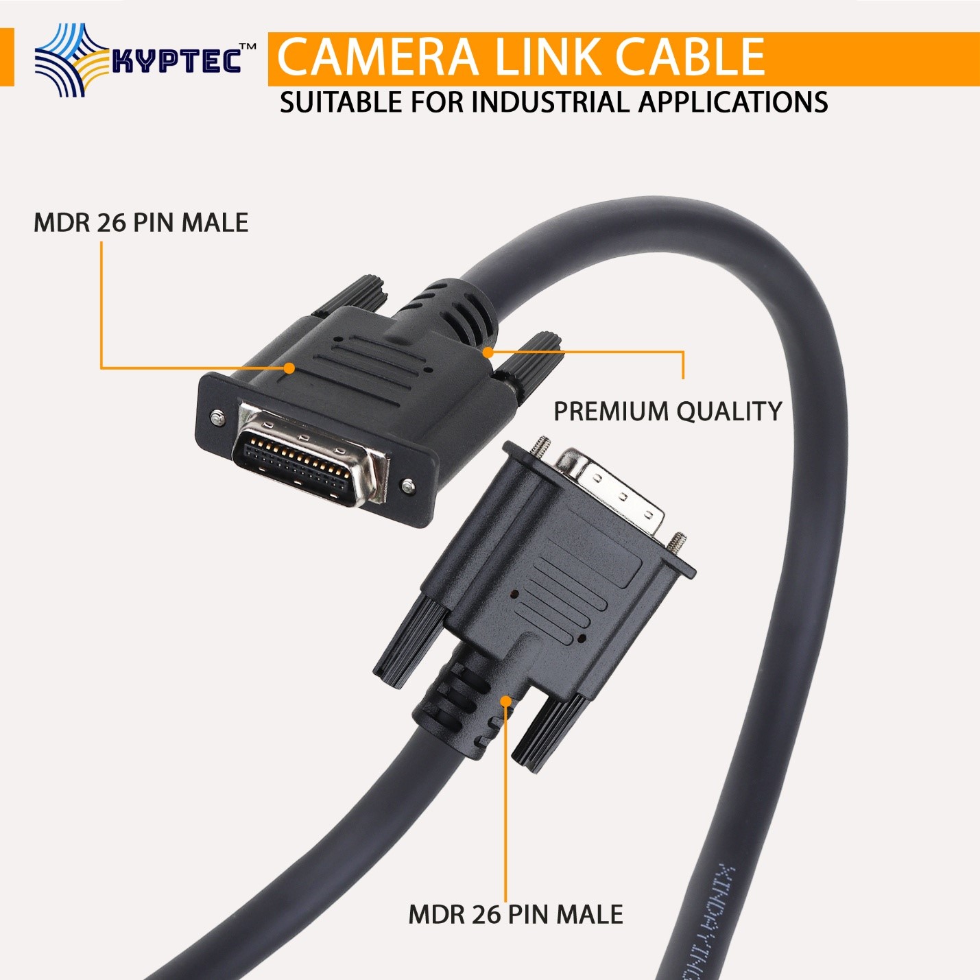
Where both compatible endpoints use MDR 26 connectors, Kyptec Automation® provides an MDR 26 male to MDR 26 male connection with retaining screws at both ends. Where the camera or acquisition hardware uses different connector formats, an SDR 26 male to MDR 26 male cable provides the corresponding mixed endpoint arrangement. The company also offers SDR 26 male to SDR 26 male connectivity where both compatible devices use SDR connectors. These three configurations create a practical selection structure for machine builders because the exact endpoint combination can be documented directly in the machine bill of materials.
Connector security is particularly important in industrial installations where machine vibration, maintenance activity, cable movement, or repeated service access can place mechanical stress on camera connections. Retaining screws help maintain the physical connection between the cable and equipment, while correct cable support reduces unnecessary load on the camera and acquisition ports. Cable routing should therefore be planned together with the camera bracket, machine frame, cabinet location, and frame grabber position. Kyptec Automation® Camera Link products are offered in standard 2 metre, 3 metre, and 5 metre lengths, with other lengths available on request, enabling OEM engineers to select according to the final installed route rather than relying only on straight line distance.
The broader Kyptec Automation® machine vision cables portfolio supports Camera Link alongside GigE Ethernet, M12, and USB 3.0 connectivity. The company is deliberately separating these interface families because each represents a different system architecture. Camera Link typically creates a direct connection between the industrial camera and compatible frame grabber, while other interfaces may follow different host, network, power, connector, and installation requirements. Clear separation between interface families allows engineering teams to specify the correct communication technology before determining connector type and cable configuration.
“Camera Link cable selection should begin with the complete camera and acquisition architecture, not with the appearance of the connector,” said Nitin Aggarwal, Co Founder and CEO of Kyptec Automation®. “OEMs need to confirm whether the system is Base, Medium, or Full, identify the connector at the camera, identify the connector at the frame grabber, determine whether one or two cables are required, and then document the exact cable arrangement. Our objective is to give machine builders a structured Camera Link portfolio that supports this engineering process and reduces ambiguity during procurement, production, and service.”
For Medium and Full Camera Link systems, port mapping becomes especially important because two physical cables operate as part of one coordinated interface. The two cable paths should be documented clearly so service teams know which camera connector corresponds to which acquisition connector. Permanent identification, consistent cable labeling, documented port assignments, and controlled replacement specifications can reduce uncertainty when equipment is disconnected and reassembled. This level of planning is particularly valuable for OEMs producing repeated machine platforms because a validated cable architecture can be carried into future builds rather than recreated for every installation.
Camera Link standardization can also improve procurement and lifecycle management. Instead of placing a generic description such as 26 pin camera cable into the bill of materials, an OEM can record the exact interface configuration, connector combination, cable length, quantity, and connection role. This creates clearer purchasing information, reduces the possibility of incorrect substitutions, simplifies spare inventory, and helps service teams maintain the validated machine architecture throughout the operating life of the equipment.
By strengthening its Camera Link portfolio around MDR 26 and SDR 26 connectivity, Kyptec Automation® is expanding its specialist authority within industrial camera communication and machine vision system design. The company’s approach connects Camera Link configuration, connector selection, frame grabber compatibility, cable quantity, mechanical installation, OEM standardization, and service planning within one engineering framework. As industrial imaging systems continue to demand reliable and repeatable data acquisition, Kyptec Automation® is positioning its Camera Link cable portfolio as a defined connectivity platform for OEMs, system integrators, and machine builders developing advanced machine vision systems worldwide.
CONTACT US:
Kyptec Automation®
C/o BalaJi MicroTechnologies Pvt. Ltd.
(A Unit of B.B. Group Of Companies)
NO# C-79, UPPER GROUND FLOOR,
DDA SHEDS OKHLA INDUSTRIAL AREA,
OKHLA PHASE-1, NEW DELHI-110020, INDIA
Email ID: [email protected]
Website: https://www.kyptec-automation.com/
Mobile/WhatsApp: +91-9217165630
(ADVERTORIAL DISCLAIMER: The above press release has been provided by VMPL. ANI will not be responsible in any way for the content of the same.)